6 Euler diagram
Euler diagram plots do not display empty intersection regions when possible, giving more concrete and accuracy visualization. Theoretically, it could have better visualization effects for more sets than Venn diagrams. And it could clearly show the fully-containing-relationships among 2 or several sets (Fig 6.1). In EVenn, Euler diagram generates area-proportional diagrams, in which the sizes of intersection areas positively correlated with number of intersection elements. This gives more perceptual intuition than only showing numbers.

Figure 6.1: Illustration of fully contained sets using the Euler diagram.
6.1 Two types of input ways
Euler diagram supports two types of input. One is the two-column mode format matrix as we described above (Fig 3.1 A).
The other is a count matrix also with two columns (Fig 3.1 F). The first line would be treated as the header line. The first column containing intersection parts of all sets by rows and the second column containing the number of elements in each intersection part. The & symbol in the first column represents intersecting. The column separator should be one TAB.
6.2 Pasting two-column mode data matrix
Here we use an animation showing the simple steps of generating the Euler diagram with pasted two-column matrix (Fig 6.2).

Figure 6.2: Animation illustrating the steps of generating Euler diagrams with pasted data matrix.
We split these steps separately.
- Select one and only one data format (Fig 6.3 1 and 1 radio button). Supposing we select
Two-column mode matrix. - Paste your data matrix in two-column mode to the text-area (Fig 6.3 3) or select one uploaded file (Fig 6.3 4) (See section 2 for data uploading.).
- We assume the
firstcolumn containselementsand thesecondcolumn containssetsname and will automatically get the names of each column to fill in (Fig 6.3 5 and 6). If your data matrix does not follow this assumption, one are allowed to change values of these two drop-down selection boxes. - Click
Submit(Fig 6.3 7) and the result would be shown in thePlot area((Fig 6.3 8). The result inPNGformat showing below and could be saved by right clicking on the picture). The result picture could also be downloaded inPDFformat by clickingDownload PDFbutton.
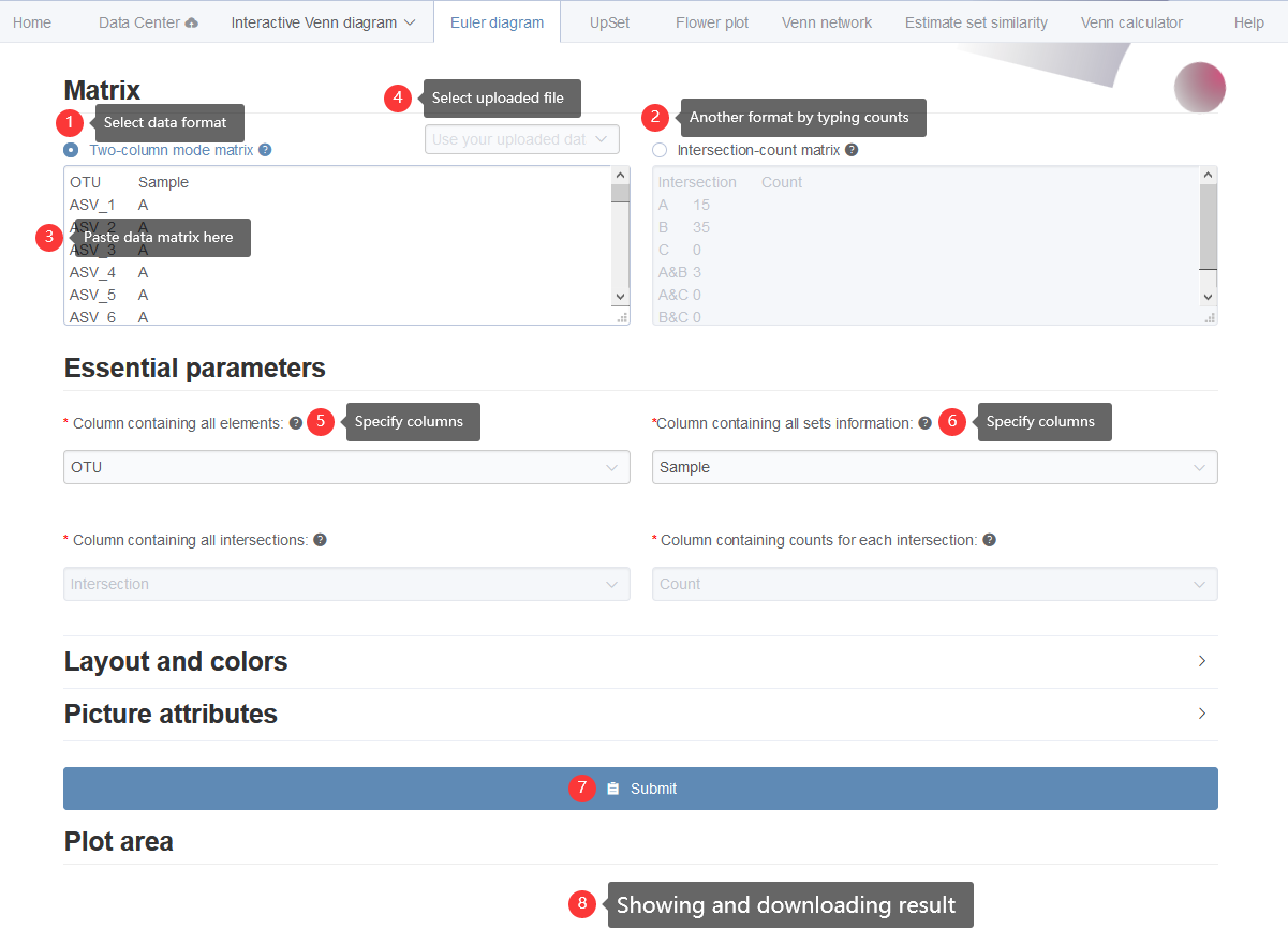
Figure 6.3: Displaying the steps for generating Euler Venn diagrams with pasted data matrix in two-column mode.
6.3 Additional style parameters
Here lists more style parameters for customized usages.
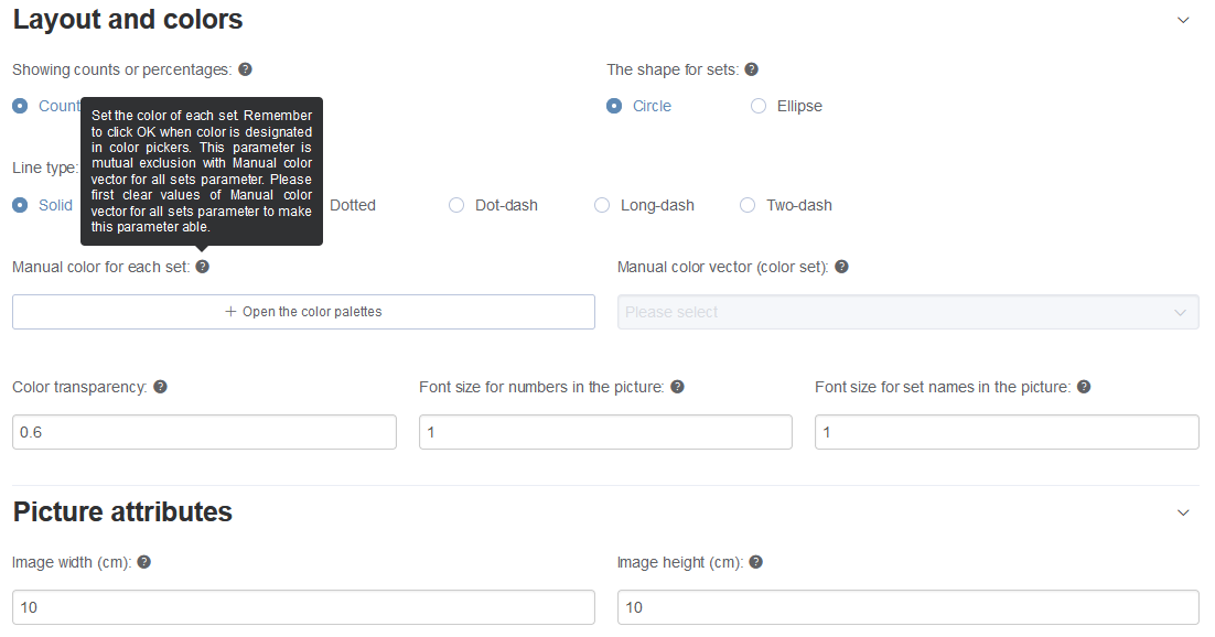
Figure 6.4: Lists of more parameters. Hovering over the question mark to see detail information.
The width and height of output picture could be modified. Enlarge these numbers if the graphic displaying is incomplete.
Most parameters could be selected very easily. Here we only explain the color setting parameters.
Here we supplied two ways to defined colors: Manual color for each set and Manual color vector (color set).
Manual color for each set: Set the color of each set. Remember to click OK when color is designated in color pickers (Fig 6.5 and Fig 6.6). This parameter is mutual exclusion withManual color vector (color set)parameter. Please first clear values ofManual color vector (color set)to make this parameter able. If you want to assign color for each set, same number of colors should be picked. If the number of picked colors less than number of sets, the program would generate intermediate colors to make they equal.Manual color vector (color set): Select the color vector for all sets. This parameter is mutual exclusion withManual color for each setparameter. Please first clear values ofManual color for each setparameter to make this parameter able.
Attention: In each way, the number of color is not needed to be the same as number of sets. The underlying program will try the best to deal with color assignments.
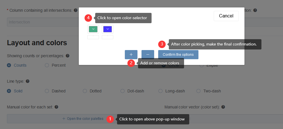
Figure 6.5: The way to set colors manually.
Figure 6.6: An animation showing adding, picking, removing and clearing colors.